top of page
Algorithm
The Essentials
The algorithm is the brains of the prosthetic. It is the code run by the Arduino microprocessor that controls the function of the prosthetic. Understanding the algorithm is key to ideal functioning of the prosthetic.
The algorithm is responsible for processing the data from the EMG sensors. The sensors read muscle movements and output voltages (after some onboard signal processing, see Electronics) which are read by the Arduino. The algorithm then decides what to do with the signals. The goal is to recognize inputs that are specific motions on the part of the user and translate them into motions of the prosthetic.
Many other prosthetics have a single EMG sensor, allowing for two motions, triggered by activation of the sensor and the previous state of the prosthetic. A wider range of motions is accessible through switching modes, either through pressing a button or moving the thumb of the prosthetic. Our prosthetic (currently) uses three EMG sensors, allowing for full functionality with no extra input from the user.
Our algorithm is suited to each individual. Here a distinction must be made between motions made by the prosthetic (from here, motions) and motions made by the user (from here movements). Theoretically, our algorithm allows for infinite motions, although realistically around four will actually be able to be made by the user. The number of motions actually available is dependent on the user's control of their muscles in the remaining stump. The user must be able to make a consistent and repeatable movement for each motion. This depends on the skill of the user, which can be improved through training and physical therapy. Our algorithm GUI allows better analysis of the user's abilities and can allow maximal use out of the prosthetic.
The motions made by the prosthetic are not required to correspond to the same motion made by the muscles. This is key as amputees may or may not have the required muscle memory to make the corresponding movements. This varies between people and can depend on the cause of the amputation, whether as a result of an accident, birth defect, or other reasons.
So how does this work? We use the GUI to analyze how many movements the user can consistently make. This information is fed (on assembly and initial setup) into the code loaded on the Arduino. We have a list of motions in order of importance that we think the prosthetic should be able to make, although this can be altered in the code by someone with the skills to do so. Each motion must correspond to a single user movement.
For example, if you can consistently make two movements, the minimum required, the two motions available for the prosthetic will be opening and closing all fingers simultaneously. During calibration (this happens every time you turn on the prosthetic, more about this later) the prosthetic will signal you to make the first movement that you want to correspond to the first motion. You repeat this movement multiple times to calibrate the prosthetic and then move on to the next motion. The order of the motions stays the same. The movement that the user makes to activate that motion does not have to stay the same (although we recommend consistency) and will be different for different people. Theoretically, you could control the prosthetic with any three sensor inputs that could be consistently controlled, i.e. you could mount the EMG sensors on the other arm...although there is no reason to actually do this.
As the user becomes more proficient at controlling their muscle movements, more motions can be added.
The algorithm runs in two main stages:
-
Calibration: on powering up the prosthetic, calibration begins. In this mode, the user makes the muscle movements they want to be associated with the motions in order. The algorithm processes the incoming data and stores it to build a probability based model that will allow it to classify sensor input during runtime. Calibration can be skipped by pressing a button, and the algorithm will default to using the last set of data stored to build the classifier. The algorithm only stores one set of data which is overwritten each time. Once, begun, calibration cannot be skipped.
-
Runtime: This is the main stage of the algorithm, in which the user actually uses the prosthetic. The algorithm runs in a loop, constantly reading the incoming sensor data. For every piece of data read, the algorithm checks if that point is most likely to belong to a specific motion, in which case the motors are activated and that motion is performed. The data read either belongs to one of the motions, or to nothing, in which case the prosthetic does nothing.
A more detailed description:
Since we are using three EMG sensors, the microcontroller reads three inputs. This set of three inputs is read as a point in a three dimensional space, where the units of the axes are expressions of the input voltage in x, y, z (sensor 1, 2, 3) respectively. (Note that the algorithm is written completely parametrically, so more sensors could be added with very little hassle without changing the algorithm, but this makes understanding it far more complicated.) During calibration, each point read is associated with a specific motion. Then using these points (and some statistical calulations) the algorithm builds a three dimensional ellipsoid belonging to that motion. During runtime the algorithm reads input points. If the incoming point falls inside the volume of one of the ellipsoids, the algorithm understands that that motion is to be made.
The size of these ellipsoids can be tweaked easily based on the skill of the user. Smaller volume requires more skill but allows for more motions to be fit in the limited overall space.
The user can also contribute to the prosthetic by teaching it with positive feedback during runtime. If the prosthetic made a motion that correctly corresponded to the intentions of the user, the user can press a button and that data point will be added to the set that defines that motion and the corresponding ellipsoid. This allows narrowing or expanding of the motion's classifier in a dynamic fashion.
The fact that calibration is performed on startup does slow the process of putting on the prosthetic, but it is important. Over time, and even throughout the day, the conditions of the muscles and the skin change, affecting the voltages read by the microcontroller. The algorithm must be updated to reflect these changes.
The algorithm directly controls the motors opening and closing. Since we are using simple DC motors, a current based control scheme is employed. Physical stops built into the geometry of the hand, or the object being grasped, result in a larger current draw by the motors. Past a certain threshold, the algorithm will decide that the finger has successfully completed its required motion, either closing or opening.
Essentials
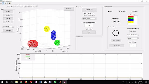
Visual representation of the algorithm from the GUI. Note the three dimensional space and the ellipsoids corresponding to four different motions
Details
The Details (for Developers)
The algorithm is written in C++ for Arduino.
Both the calibration and the runtime parts of the algorithm are based on a concept of windows and peaks.
Calibration works as follows for each motion:
The Arduino has a chosen window (an odd number) of data points that it analyzes in each given loop. These points are stored in an array (remember these are three dimensional points). During each iteration, the algorithm checks the middle point to see if it is a local maxima within that window. Each point is essentially a vector so vector norms are used to compare relative size. If the point is a local maxima, it is classified and stored as a peak. After a certain number of peaks are registered, peaks that are farther from the average norm than 25% are filtered out. The x, y, and z values of the remaining peaks are used to build the hyperspheres (in 3D these are ellipsoids) used in runtime to classify motions. In the past this process was time based, that is the user was given a set amount of time to make as many of the same motion as possible. Currently the calibration is based on the number of recorded peaks.

Visual representation of the windows and peaks method and how it filters unwanted points
The ellipsoids are built from the data set, composed of the peaks, of each respective motion. We start with a unit sphere placed at the point determined by the average x, y, and z value of the set. We use a standard formula for the standard deviation in each coordinate and stretch the sphere in each axis based on a constant times the respective standard deviation. This constant can be controlled based on the user's skill level and consistency.
During runtime, the Arduino is also using a peak based analysis. Problems resulted when every point read from the sensors was fed into the classifier, as it could result in an unintended motion being performed. Here also the algorithm analyzes a window of a number of the last points collected and checks the midpoint to determine if it is a local maxima. If so, that point is fed into the classifier. Only peaks are classified!
The size of the window being used has to be small enough so that the user does not notice delays in the response of the prosthetic, yet large enough to filter out local maxima caused by sensor noise. Peaks are only registered in calibration and runtime if they are above a certain minimal threshold.
If a peak doesn't fall in any ellipsoid, the prosthetic does nothing. If it falls in an ellipsoid, the prosthetic performs the motion belonging to that classification. It is possible for two or more of the ellipsoids to overlap. The GUI allows checking for this. If a peak falls within more than one ellipsoid, it is classified as belonging to the ellipsoid to whose center it is closer.
The algorithm is written very parametrically. At the beginning of the code the number of sensors and motions can be easily adjusted, as can the factor that determines the size of the classifying ellipsoids and the number of motors run.
Videos
Videos showing algorithm being used to successfully make two and four distinct motions
Files
Working On
Files
To view and edit the files used for our algorithm and programming you will need
-
Arduino IDE (or similar, for editing the code we recommend Visual Studio with Visual Micro)
What We're Working On
-
Implementing motor control. This requires defining motions and modifying the code.
-
Implementing more accurate current control scheme to allow definition of motions with varying grip strengths.
-
Trying a new idea for classification using cones (spherical coordinate system) and thresholds to classify peaks.
bottom of page